Physics-SchoolUK.com

The UK site for KS3 and KS4 Physics

KS4 Electricity

It would be impossible to imagine our world without Electricity! All our home and street lighting, our entertainment systems, our communication devices, our medical facilities and industrial processes rely on the continuous supply of electricity. It is vital, therefore, that we have a knowledge of electrical circuits and of how electricity is supplied to us as users.

KS4 Electricity: Current, potential difference and resistance
In this first part of KS4 Electricity we look at the basics of electrical circuit theory trying to gain an understanding of the above 3 important terms.

Introduction to Charge, Current and Potential Difference

What is an electric current?

An electric current is a flow of charge.

But what is "charge" and what is meant by a "flow of charge" ?

For a long time, Physicists didn't know the answer to the question, what is charge. All they knew was that something flowed when there was an electric current. And for want of a better word, they called that something, charge!

But now we know what actually flows when we have an electric current, so now we know the answer to the question, what is charge.

Charges are electrons. So, a flow of charge is a flow of electrons.

These are the same electrons that you will know are present in all atoms.

Now that you know that an electric current is a flow of charge, which is a flow of electrons, you should be able to figure out why it is that electrical circuits (whether complex ones like those in computers, or simple ones like those in a table lamp or a torch) always use metal wires to form the circuits (to join up all the components).

The reason is that all metal atoms have an abundance of free electrons which can be made to flow, making the electric current.
This is why we say that "metals are good conductors of electricity", because they have an abundance of free electrons which can be made to flow.
Materials such as plastics, which don't have atoms with free electrons, are not used to make circuits and we describe them instead as "good insulators of electricity".

So, a piece of metal wire is ideal for carrying an electric current; it is literally full of electrons. We can think of them, as in the following diagram, like cars, bumper to bumper.

The electrons in the wire above are not moving or flowing, so there isn't a current.

What else is needed in order to produce the electric current, to make the electrons or charges flow?

To produce an electric current in the wire, there must be a Potential Difference across the wire.

Batteries and mains electricity are two sources of Potential Difference.

In the following diagram a battery is being used as a source of potential difference and it is connected across the piece of wire.

The battery seems to push on just one electron, but since the electrons are "bumper to bumper" in the wire, like the cars, they ALL move through the wire as shown by the arrows in the diagram.

The best way to think of the source of p.d (potential difference) is as a pump.

Just as a water pump takes in water at one end and pushes it out at the other end, so our source of p.d takes in the electrons/charge at one end and pushes them out at the other end, causing all of the electrons in the circuit to move or flow at the same time! It is important to understand this.

As long as the source of p.d remains doing its job, the electrons keep flowing and we have a steady electric current flowing all the way around the circuit.

Note: The last 6 words in Bold are really important; the current flows steadily, continuously, all the way around the circuit, through whatever components are in its way. So whatever is the size of the current leaving one side of the p.d source will be the size of the current entering the other side of the p.d source. More on this later.

So, to summarise:

Before we end this introduction, let's take the opportunity to talk about 3 things mentioned in the above summary list that can be measured.
These are the size of electric current, the quantity of charge and the potential difference (also known as voltage).

The size of electric current is given the symbol "I" and it is measured in units called amperes or amps or A.
eg I = 3 amperes, I = 3 amps, I = 3 A, all mean that the size of the current is three amperes.

The quantity of charge is given the symbol Q, for Quantity. It is measured in units called coulombs or C.
eg Q = 1200 coulombs, Q = 1200 C, both mean that the quantity of charge that has flowed is 1200 coulombs

The potential difference or voltage is given the symbol V. It is measured in units called volts, which unfortunately also has the symbol V.
eg V = 10 volts, V = 10 V, both mean that the voltage or potential difference is ten volts.

This is enough for our introduction.
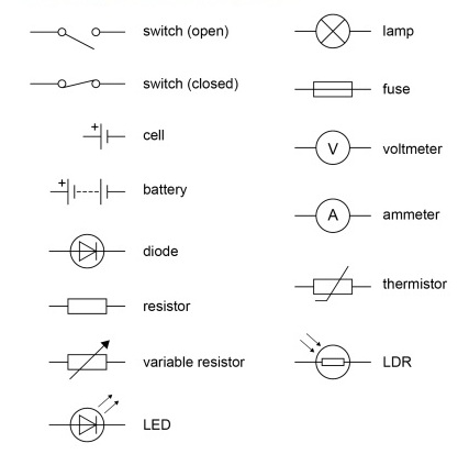
Standard circuit diagram symbols

In the diagram above we show the battery as a rectangle with two connections at either end. Now, whilst it might resemble some types of battery it does not resemble all types of battery and not everyone will recognise it is a battery!
For this reason, we use "standard circuit diagram symbols" so that everyone will know what is meant when someone draws a battery or other circuit component.

Drawing the above diagram using standard circuit diagram symbols, we get this:

Although we can no longer see the charges (electrons) we know there is a current flowing because there is a current flow symbol, the arrow head, and next to it the letter I which is used to tell us the size of the flow of current (more on this below). The arrow head is especially useful because it shows us the direction of the current flow; in our diagram it is clockwise, isn't it, because current always flows from the + side of a battery or cell.
Notice also the letter V above the battery symbol. This is used to tell us the size of the Potential Difference (also known as Voltage, remember).

Of course, there are many other circuit diagram symbols.
You need to know quite a few! So here are the ones you need:

One final comment on circuit diagrams.
When you draw one:


In other words just like the diagram above; never like this......

Electrical charge and curent

This section of the AQA specification focuses on two of the important statements alrady made in the Introduction, above:

Electric current is a flow of electrical charge.
And
For electrical charge to flow through a closed circuit the circuit must include a source of potential difference.

Having got those two statements repeated, we can move on to say something new!

The size of the electric current is the rate of flow of electrical charge.

"...rate of flow of electrical charge" means - the amount or quantity of charge, which flows in a certain time.

If we use the letter Q to represent the quantity of charge, and the letter t for time, then we can turn the above statement into an equation (remember, in the section above, we said that the letter I is used for size of current):

Since this equation involves three terms, then it can be rearranged, for example we can re-write it to find Q:

OK, that is enough calculation questions for now.
Before we move on to the next section in the AQA syllabus, one more point about Current -

When we draw a simple circuit, consisting of a single loop, such as below, we can put our current symbol "I" and our arrow head anywhere on any of its 4 sides.

This is because the current has the same value at any point in a single closed loop circuit.

To understand this, remember that an electric current is a flow of electrons through a conductor so if we measure the currents at the two points in the diagram above, we will find that it is the same.

The same electrons must flow past each of the points at the same rate because they are all moving "bumper to bumper"!.

It is a bit like standing at the side of a fairground roundabout (you know, the type with the wooden horses that young children sit on); if you measure the rate at which the horses pass you, then you move to the other side of the roundabout and make the same measurement, you will measure exactly the same rate, the same "flow of horses".

So learn this important point:
the current has the same value at any point in a single closed loop circuit.

The size of the current in a circuit

What determines the size of the current in a circuit?

The size of the current in any circuit depends on just 2 things:

  1. The value of the potential difference (p.d), V, connected across the circuit.
  2. The total resistance, R, of the circuit.

(Resistance, by the way, is measured in a unit called "ohms" and is given the symbol Ω which is the Greek letter "omega").

Let's think about the first of these 2 factors, the value of the p.d, V :

It seems pretty obvious that a larger battery (a larger p.d) will cause a larger current to flow in a particular circuit, don't you agree?
Consider the following circuits.

The circuits above have the same resistance (because they have identical components, 2 lamps connected in the same way)
But the circuit on the right has a larger p.d, causing a larger current.
In fact, because the p.d is double that of the circuit on the left, the current is also double.

So, Current I increases as p.d V increases. Easy!

We can write this using an equation with the proportional sign:
I ∝ V

In words we say this as "Current is proportional to P.d (or Voltage)".

Now let's think about the second factor, the effect of the total resistance, R, of the circuit:

Any component that gets in the way of the flow of current presents a "resistance" or an opposition to the flow of the current.

So, in the following circuit, where there is one lamp, there is a "resistance" in the circuit (an opposition to the flow of current) due to the single lamp.

In the next circuit there are two lamps (each one identical to the one in the first ciruit), so there is twice as much resistance to the flow of current from the battery (which has not changed).

So, which circuit will have the largest current, the one with the lowest resistance (circuit 1) or the highest resistance (circuit 2) ?

Hopefully you have got it correct!

The effect of the 2nd factor can be summarised as:
The larger the total Resistance of a circuit, the smaller the current in the circuit.

Or, using the proportional sign, we can write:
Current, I ∝ 1/R

In words we say this as "Current is inversely proportional to Resistance".

Not surprisingly, you need to be able to use any of the 3 versions of the equation to solve problems, so let's have a go at a few examples.

Resistors

All components "resist" the flow of electric charge, or resist the flow of current, so all components can be called RESISTORS.

You need to know about 3 particular components and about how they behave as resistors.

To investigate their behaviour as resistors we are going to use the simple bit of knowledge that we have about resistance, which is our equation:
R = V/I ,
or in words:
Resistance = Voltage / Current

What we will do is build a circuit where we will be able to measure the Voltage (or p.d) across our component whilst measuring the Current flowing through it. The following circuit allows us to do this.

If necesssary, look back to the picture of the circuit symbols to identify the Ammeter, the Voltmeter and the "variable resistor". This final component is used to vary the current flowing through the component being tested, allowing the p.d across the component to be investigated as the current changes.

Being able to vary the current through the component is really useful because it allows us to get a range of Currrent and Voltage readings for a component rather than just one pair of readings which would be the case if we couldn't vary the current.

If we add a 3rd row to the table to show the calculation of Resistance, R, for each pair of values, then for this component we get:

So this particular component is one whose resistance remains constant no matter how the current through the component, or the voltage across it, changes.

Another way to make use of the table of data values is to use them to plot a simple graph of Current against P.d.

The straight line tells us that the Resistance of the component is CONSTANT.

So, what is this component?

It is a Resistor, whose resistance is constant and its fancy name is an "ohmic conductor".

Another way of stating that the Resistance is constant is to say: "The current through an ohmic conductor is directly proportional to the potential difference across it".
We find that this is true so long as the temperature of the component remains constant.

A simple example of an "ohmic conductor" is just a piece of wire, or any piece of metal such as a bar of aluminium.

The last thing to say about these resistors is that if you reverse the p.d across them then the current flowing through them simply reverses as well, but the resistance remains constant. We can illustrate this on a modified graph as shown below:

When we draw graphs like this we call them "Characteristic Curves", so the above graph is a "Characteristic Curve for an Ohmic Conductor", such as a piece of wire.
What we mean is that ALL ohmic conductors share this "characteristic curve".
The slope of the line may differ for different ohmic conductors (eg different lengths of pieces of wire) but it will always be a straight line.

So, now we know about 1 type of Resistor, the Ohmic Conductor. There are 2 more to discover, but we've done the hard work, so this won't take so long.

Second Resistor: The Filament Lamp

Here is the Characteristic Curve for a filament lamp:

As you can see, unlike the previous "ohmic conductor", the filament lamp has a resistance which is NOT CONSTANT; the Characteristic is a very definite CURVE, not a straight line.
The current is not proportional to the p.d.

Why is this?
What is going on inside the filament lamp to cause its resistance to change as the current increases?

The answer is quite simple.
When the current through the lamp is small, the lamp glows dimly, so its at a low temperature.
When the current through the lamp is increased, the lamp glows brighter, so it gets hotter and its temperature increases.
If the current increases further, the lamp glows even brighter and the temperature rises even higher.

So, unlike an Ohmic Conductor; for a filament lamp, as current increases, the temperature is NOT CONSTANT. Instead it increases and because of this, the resistance also increases. This shows up on the characteristic curve as a decrease in the slope of the line. (Think about the equation, R=V/I)

This gives rise to the Filament Lamp's characteristic "S" shaped curve.

Third Resistor: The Diode

Here is the Characteristic Curve for a diode:

The Diode is our most unusual "resistor" of the three that you need to know.

If you studied the diagram of "Circuit Symbols" earlier on this page, then you will have gathered that there was something a bit odd about the Diode.

Its symbol is more complicated than other components:

The symbol and the characteristic curve tell us that the current flows only one way through the diode.
The current only flows in the direction of the "arrow" in the symbol and not against the "barrier".

So, current will only flow through a diode when a battery is connected like this:

Current flows through the whole circuit (notice the current arrows), making the lamp light.
On the characteristic curve, this is the right of centre region where the resistance of the diode is low and current flows.

If, however, the battery terminals are reversed:

When the battery is connected like this, we say that the diode is "reverse biased"; it is trying to make the current flow against the direction of the "arrow" and through the "barrier", which it can't do (notice there are NO current arrows).
On the characteristic curve, this is the left of centre region, where no current flows and the resistance of the diode is VERY high.

You might be wondering, Where are diodes used?

Diodes can be used in situations where it is important to only allow current to flow one way.

In basic "lamp" circuits it doesnt really matter which way the current flows in order to make a lamp light, but in almost all complex electronic circuits, from those used in mobile phones, to laptops, to TVs, it is vital to control the direction of current flow otherwise sensitive components can be destroyed!
So all of these devices are protected with "reverse polarity protection diodes". In the old days, before the use of these diodes, if you put batteries into a device the wrong way round and pressed the on button, your device would be irreversibly damaged! Today, with the use of reverse polarity protection diodes, all that would happen is that it wouldnt turn on until you realised that you had put the batteries in the wrong way.

In the 1st circuit above, the battery polarity is correct and the diode allows the current to flow, as shown, so the device operates normally.
But in the 2nd circuit where the battery polarity has been reversed, the diode prevents current flowing, so the device just doesnt operate, but is protected.

Other Types of Resistors

There are 2 other types of resistors that you need to know about: Thermistors and LDRs.

Thermistors

Thermistors, as their name should suggest, are resistors whose resistance varies with temperature.

For most thermistors, their resistance decreases as the temperature increases.

So, a thermistor is a temperature sensitive resistor, making it an ideal component for use in electronic thermometers, thermostats and some fire alarms (detecting temperature rise, not smoke!)

LDRs: Light Dependent Resistors

LDRs, as their name suggests, are resistors whose resistance varies with light intensity.

Like the Thermistor, the resistance of the LDR also decreases, but as light intensity (not temperature) increases. So the graph to show this is remarkably similar to that for the thermistor (be careful not to confuse the two).

LDRs have a number of obvious uses. For example in electronic circuits to detect changes in light level in order to turn on security lights or street lights. Also to measure light intensity in camera (and mobile phone camera) automatic exposure systems.